One of the common tools that researchers use to measure temperatures of objects or organisms is the electronic thermocouple. For a few hundred dollars you can have a handheld electronic thermocouple reader and flexible thermocouple leads. The thermocouple readers are quite durable and last for years. On the other hand, the thermocouple wires eventually break after lots of usage. Most people purchase pre-made thermocouples from a source such as
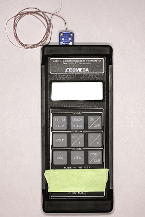
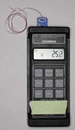
Omega Engineering primarily for the convenience/cost tradeoff. However, it is fairly easy, if somewhat time consuming, to make and repair your own thermocouple leads using supplies from Omega, which can save money in the long run compared to purchasing new thermocouple leads every time you break one. This tutorial is based around the assumption that you have one of the typical Omega handheld thermometers (pictured above) and use T-type thermocouples with “miniature” connectors.
If you or your lab have standardized on some other type of thermocouple, maybe K or J type, perhaps using “standard” round-pin connectors, you can still use the same principles described here, but the part numbers will differ.
When I aim to measure temperatures of inverts and algae, rock temperature, or the air temperature in the field, I use T-type thermocouples with wire of a few sizes. For now we’ll consider fine-gauge wire as it is the most versatile (but least robust) form for measuring temperatures of small things. It’s always desirable to be able to say that the thermal mass of your measurement instrument doesn’t influence the temperature of the object you’re measuring (i.e. placing a large stainless steel temperature probe at 20°C on a small snail at 40°C might cool the snail during the measurement process), so using small diameter thermocouples is good.
It can make sense financially to purchase thermocouple wire in bulk so that you can make and repair thermocouples for years to come. For instance, you can purchase 40-gauge T-type insulated wire from
this page on Omega’s web site. The particular wire I would order is part number
TT-T-40-SLE-100. This part number would get you 100 feet of 40-gauge T-type thermocouple wire with a "Neoflon" insulation. Note my recommendation for getting the “Special Limits of Error” wire rather than regular wire. It costs a bit more, but Omega specs this wire to a higher standard, so that it should be within 0.5C of the actual temperature, rather than the 1C of the regular cheaper wire, even before you calibrate.
To go with the wire, you’ll need to purchase the connectors that allow you to plug the wire into your handheld thermometer, and in this case I recommend connectors from
this page, using this part number combination in particular:
HMPW-T-M. For starters you only need the male plugs to plug into your handheld thermometer, but you can use the female plugs to make "extension cords" by placing a female plug at one end and male plug at the other end of a length of thermocouple wire. If you have a pile of old non-functional thermocouple leads sitting around, you can reuse the connectors.
With the wire and connectors in hand, you can now start making your own thermocouple leads. To put things together, you’ll need the following equipment:
Soldering iron and regular solder for electronics
Dissecting scope or magnifying glass so you can see
Razor blade or scalpel
Small screw driver, such as a jeweler’s screwdriver
Fine forceps
Some tape
Assembling the thermocouple:
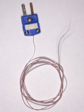
Start by cutting off a length of thermocouple wire to the desired length. I usually make my leads a few feet long (3-4’). We’ll start by attaching the leads to the plastic connector.
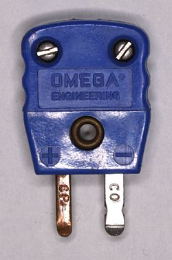
Unscrew the cover on the connector. Underneath you should see two screw terminals.
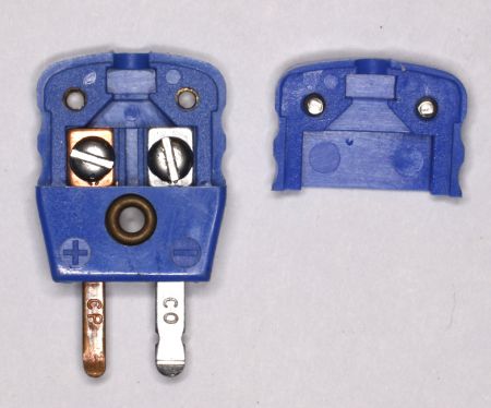
On a T-type connector, one terminal will be copper colored and the other will be silver colored. They each have a screw in them, which is how you will attach the thermocouple wires. Unscrew the terminal screws. Sometimes your connectors will have little Teflon washers under the terminal screws, or maybe a metal flange to help hold the wire down against the terminal. You can use these during reassembly, or discard them.
Take your thermocouple wire and place one end under the dissecting scope. I like to use a bit of scotch tape to hold the wire in place so that I can work on it with both hands. While looking through the scope, take a sharp razor blade and scrape off some of the insulation from the wire.
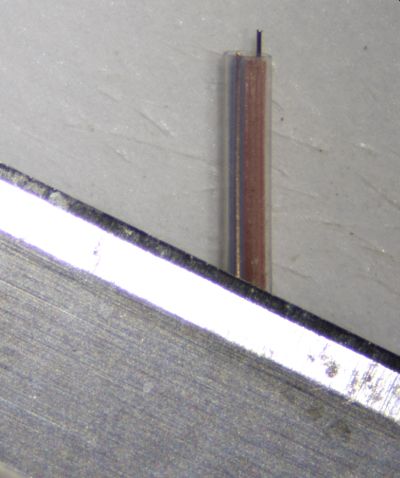
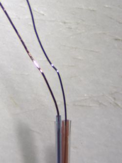
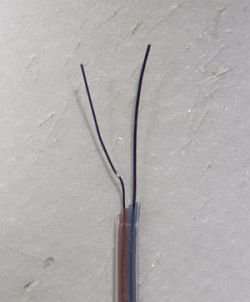
With the thermocouple wire I recommended above, there is a clear outer jacket, and then separate red and blue insulation around the copper and constantan wires. Place the razor blade at a shallow angle to the wire (i.e. nearly horizontal) about 1” from the end, and scrape towards the end of the wire. Do this gently to avoid cutting through the metal wire itself. You just want to take off the clear insulation and the colored insulation, leaving the bare wires intact. The 1” length gives you plenty of bare wire to wrap around the terminals in the next step. Cut away the excess insulation so that things are neat and tidy.
Once you have your wires bared, bring in the connector. Again, this is probably best done under the scope. With your wire still taped down, position the connector so that the bared portion of the wire will sit completely inside the connector when closed.
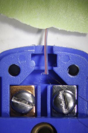
Then use your forceps to wind the bare wires around their respective terminal screws.
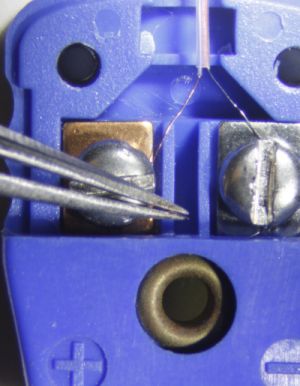
The wire color matters here: the copper colored wire needs to be screwed onto the copper-colored terminal, while the silver constantan wire needs to be screwed onto the silver terminal (again, this assumes you’re using T-type thermocouple wire). Follow this up by carefully screwing down the terminal screws. It is fairly easy to accidentally break the wire at this step, especially if the wire catches on the terminal screw and starts tugging as you screw down. Use your forceps to keep everything in place. The goal here is to get the bare wire of the thermocouple lead in direct contact with the terminal, using the screw to push the wire down onto the terminal. Also note that your two bare wires should not touch each other inside the connector housing, so keep them separate!

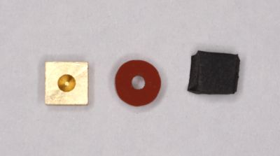
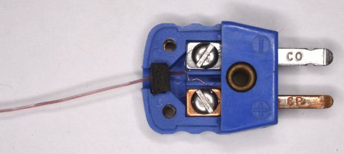
With the wires screwed down, it’s time to add in a strain relief before replacing the plastic cover on the connector. The connectors from Omega sometimes come with square brass or copper pieces that sit in a depression at the distal end of the connector housing to act as a strain relief. Typically these pieces simply sever the fragile wire as you screw the connector cover back on. Alternatively, the connector may come with a round brown silicone rubber piece with a hole through its middle. This hole is too large to grip the very fine 40 ga wire, but works fine on larger diameter wire. You can make use of the silicone rubber piece by slipping the wire underneath the rubber so that it is pressed between the rubber and the plastic of the connector case. In either case, I always just replace the square metal pieces or round rubber piece with a similarly sized square piece of rubber that sits in the depression.
The rubber grips the thermocouple lead without cutting it, providing a measure of strain relief for the terminal connections inside the housing. I cut out little pieces of neoprene rubber purchased from
McMaster-Carr, such as the rubber in this assortment: part number
9455K666 found on
this page.
At this point the thermocouple is half finished. You now need to complete the junction at the far end of the thermocouple lead, where you’ll be measuring your temperature. We typically use solder to make this connection, as it is easy and fairly durable. The pre-made connectors you buy from Omega use a welded junction at the sensing end, which is more durable than solder, and will not melt at high temperatures. Soldered connections are fine for the full range of biologically-relevant temperatures you’ll find in the field, but you couldn’t use a soldered joint to measure the temperature in your muffle furnace for example, as the solder would melt.
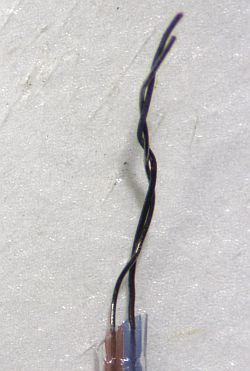
As before, you need to bare the thermocouple wires to make the connection. Tape your wire down to the dissecting scope platform, and use your razor blade once again. I recommend only baring ~1/4” or so. In special cases you might want a long bare wire lead, but for most purposes a short bare section at the sensing end is desirable from a durability standpoint.
With the two wires bared, use your forceps to twist the two leads together.
This provides a bit of mechanical strength to the joint, and makes the soldering easier. For the soldering step, fire up your iron, clean the tip (wipe it on a wet sponge), and melt a bit of solder onto the tip. Again, this next step is best done under the scope. Take your soldering iron and touch it to the twisted wire pair. If you have enough solder on the tip of the iron, the wire pair should be “submerged” in solder.
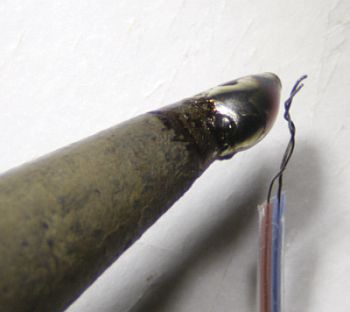
I then draw the iron tip out towards the end of the twisted wire pair, dragging the solder pool along the twisted wires. Solder doesn’t stick well to the wire pair, so ideally the twisted joint will retain a bit of solder on the two wires via surface tension. Do this quickly (touch iron tip to wires, draw iron tip towards end of wires) until a bit of solder remains.
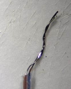
It doesn’t take much to hold the wires together. Once you have some solder on the joint, you can test the thermocouple by plugging it into your handheld thermometer. You should get a temperature reading, and it should quickly approach air temperature if the tip of the thermocouple is sitting free in the air. Assuming the thermocouple gives you a reading, you can now trim off any excess bare wire from the tip that you don’t think you’ll need, using the razor blade or wire clippers. Occasionally you’ll end up with a big blob of solder on the tip, and I like to cut that off to keep the tip low-profile.
You should now have a working thermocouple.
It would be prudent to calibrate your thermocouple lead. At the very least, dip your thermocouple tip in a stirred ice water bath to get a 0 degree C reading, and go find a water bath or some other warm water of a known temperature (a calibrated alcohol thermometer would be useful here) and check your thermocouple against the water temperature. Each thermocouple lead that you make may have a slightly different calibration, so it’s worth checking them and writing the calibration on a piece of tape that you stick on the thermocouple lead. Most of the time your thermocouples will all read within 0.1°C of each other, but some may be further off.
Now that you can make your own thermocouples, you can also repair broken thermocouples using the same methods. You might occasionally rip the wire out of the connector, or the sensing tip might get flexed too many times and break, or you might wind the wire too tightly and break it somewhere within the insulation. In every case you can just cut off the offending end of the wire and make a new, shorter thermocouple. Be sure to recalibrate it!